Oil Artifacts
I have found many oil-related artifacts through the years and have documented most of them here. The big challenge has been to attempt to identify them and figure out what they were used for. I searched through many old books, oil well supply catalogs, and other documents to look for answers. I also have to give Jeff Brantly special thanks. He is an oil relic enthusiast from Louisiana who has identified many of the relics here. I am lucky he found this site and was willing to help.
Note: The land is owned by the MRCA and it is illegal to remove anything. Take pictures not artifacts. I did take some of the smaller items before the MRCA owned the land and when the dump was being planned. I later donated them to the MRCA at the Sonia Thompson Nature Center in Towsley Canyon. I set up a small exhibit there. Unfortunately, around 2010, the MRCA closed the nature center and carted away the exhibit to some unknown location probably never to be seen again.
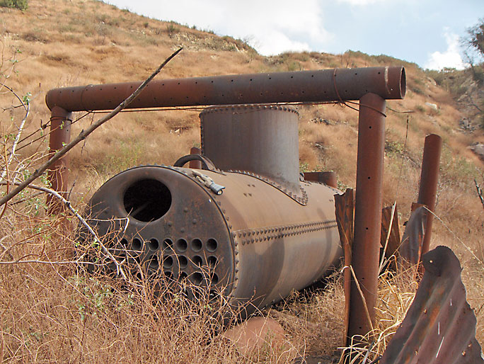
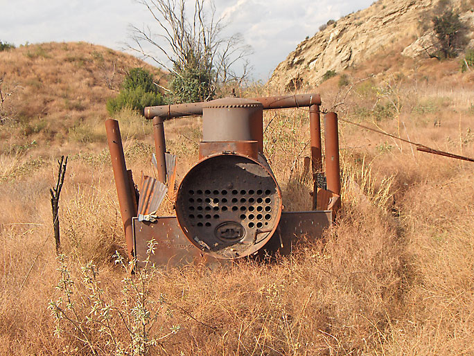
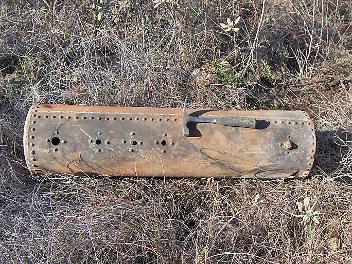
Although not physically in Elsmere Canyon, this horizontal tubular steam boiler is in the Elsmere area and should be considered as part of the oil history of Elsmere Canyon. It provided power for early cable tool rigs and/or jack pumps. This boiler is a fire-tube boiler. Hot gases from a fire pass through the tubes which run through a sealed container of water. The water gets heated, creating the steam. The tanks are usually cylindrical because this is the strongest and most practical shape for a pressurized container. Almost all steam locomotives used this type of horizontal fire-tube boiler. (Photo taken on 12/9/2006)
Jeff Brantly also points out that the perforated pipes creating the frame around the boiler were more than likely well casings. They would have been at the end of the casing string. The oil would flow though the holes into the casing.
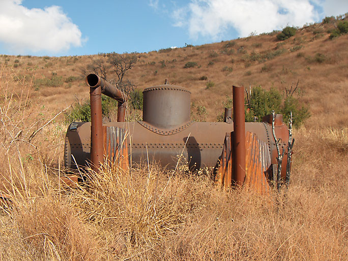
Another view of the boiler. (12/9/2006)
Another view. (12/9/2006)
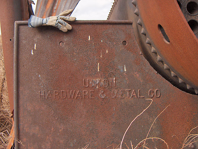
Close-up showing logo on hardware supporting the boiler. Logo says "Union Hardware & Metal Co". (12/9/2006)
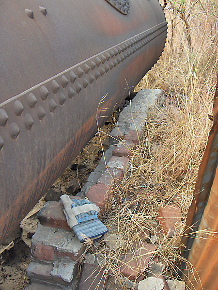
The boiler was surrounded by bricks. (12/9/2006)
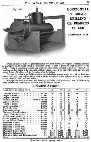
This is from the Oil Well Supply Company catalog of 1907. The dimensions of the Elsmere boiler are very similar to this boiler. The diameter is 48 inches. The overall length of the boiler is 13.5 feet. The length of the tubes are 12 feet. The diameter of each tube 3 inches. The number of tubes is 42. The diameter of the dome is 36 inches. The height of the dome is 28 inches. Based on the page from the catalog, the weight of the Elsmere boiler is about 6000 pounds.
Smokestack maybe for nearby boiler. (6/23/2007)
Another smokestack in a different area then the above picture. This is on a slope below Elsmere 20 oil well location. (8/4/2007)
Steam engine that was connected to a cable tool rig. Engines for well drilling were usually about 20 horsepower. It is pretty exposed and has been partially stripped of parts. It appears to have been intentionally placed there because there are two support pipes holding it in place. It might have been used for a jackline support (see jackplant page). (12/9/2006)
Another view of same engine. (12/9/2006)
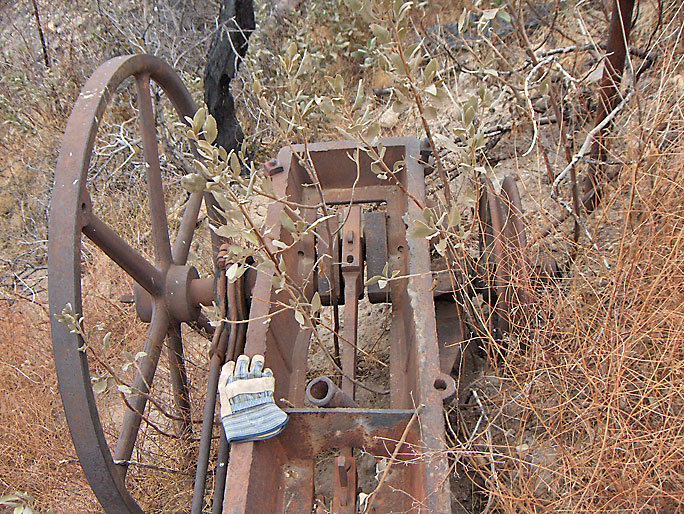
Still another view of engine. (12/9/2006)
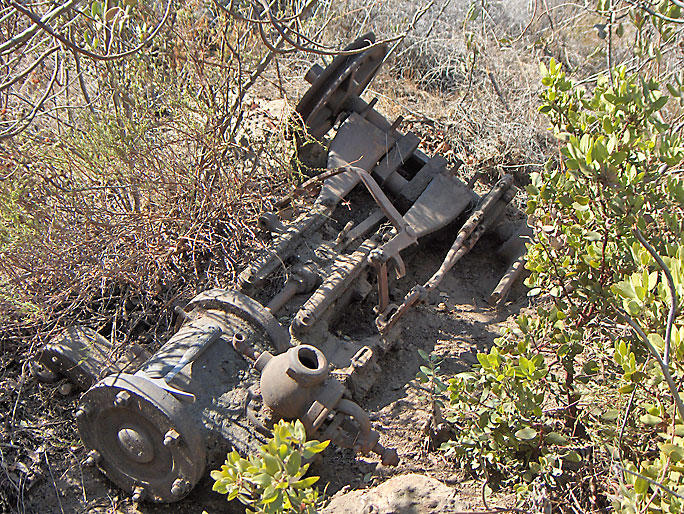
This engine is located in a heavy brush, especially poison oak, covered area. I found it more or less by accident. It is partially damaged. (9/3/2007)
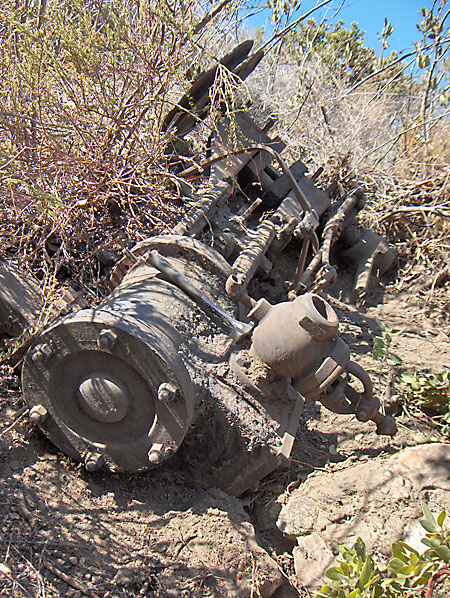
Closer view (9/3/2007)
Another view (9/3/2007)
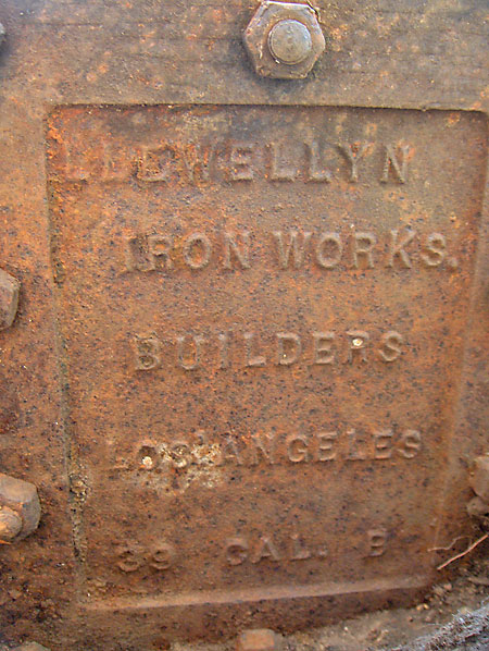
On one side of engine: "LLewellyn Iron Works. Builders Los Angeles 39 Cal. B". As explained below under the crown pulley picture, Llewellyn was merged with Consolidated Steel Corporation in 1929, so I don't think the "39" means 1939. Almost all the wells were drilled by 1939 and any productive wells were on pumps. (9/3/2007)
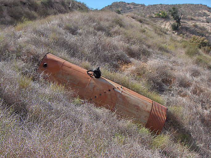
According to the dump EIR, this is a riveted sheet metal water separation ("shotgun") tank. This type of tank was used for separating oil from water. It is about 16-ft. long by 5-ft in diameter. There is a series of 9 valves arranged in even increments rising in elevation along one side of the tank. The valves, or petcocks, were used to measure and compare oil and water levels. This tank was removed during the well abandonments of late 2011-early 2012. (6/23/2007)
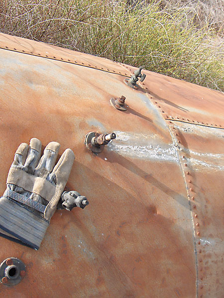
Closer view of valves on side of separation tank. There are nine valves visible here. If there are more valves on the other side of the tank, it is impossible to tell without digging the tank out of the ground. (6/23/2007)
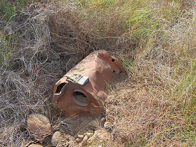
Old metal barrel with diameter of 24in and height of 30in. (6/23/2007)
Close to the barrel and separation tank is this smaller tank about 1 x 4 feet in size. (12/22/2007)
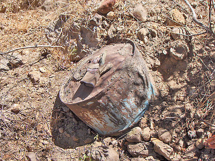
This old barrel rests partially buried near an oil well site. Even after 100 years, it still has some blue paint on it. (7/21/2007)
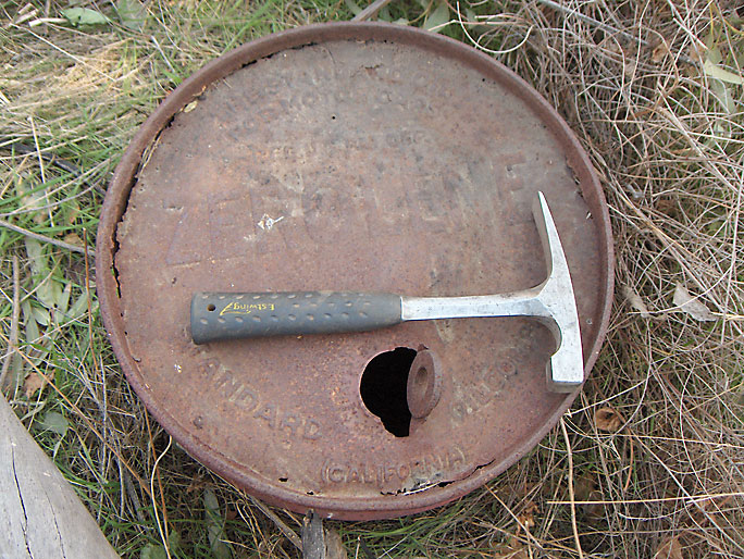
Here's an old oil can partially buried in the ground. The diameter is 16-inches but the height is unknown without digging it up, which I see no reason to do. The top reads:
The Standard Oil
For Motor Cars
Reg US Pat Off
ZEROLENE
Standard Oil Company
(California)
Zerolene was first developed in 1907 at Standard's Richmond, California, refinery. Zerolene got its name because, according to company advertisements, "the product flows freely at zero." In 1913, the product was selling 2.5 million gallons annually. By 1929, Standard launched New Zerolene oils and Standard Ethyl Gasoline. Thus, the date range for the can is probably between 1907 and 1929. (10/28/2007)
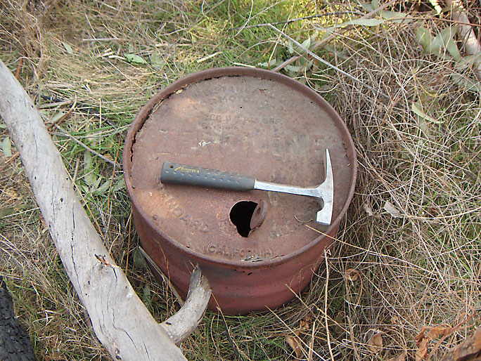
Another view of can (10/28/2007)
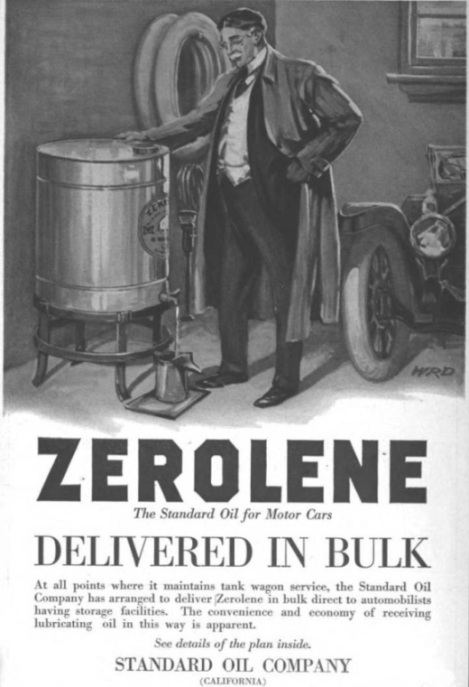
Advertisement from the Standard Oil Bulletin of August, 1913 (Vol. 1 No. 4)

This old brick is on the site of a pre-1895 well. It says:
PARKER RUSSELL
MI & MANF'G CO
ST. LOUIS
NO 1.
Parker-Russell Mining and Manufacturing Company of St. Louis, Missouri was of the nation's leading makers of fire brick. Clay deposits were discovered in the 1850s in Oak Hill, Missouri on the property of James Russell. When Russells' daughter Russella married George Ward Parker in 1854 the Parker-Russel Mining and Manufacturing Company was formed. (10/28/2007)
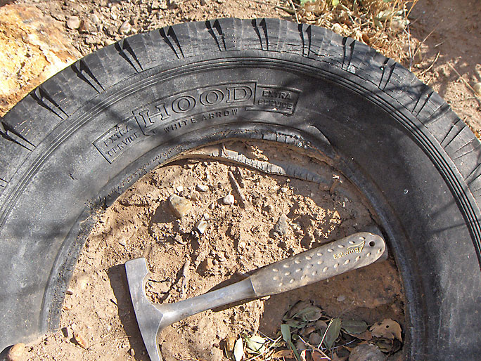
This is a circa 1920's Hood "Extra Service" White Arrow tire. Hood Rubber Company was headquartered in Watertown, Massachusetts. Its lifetime was from 1896 - 1969. (10/28/2007)
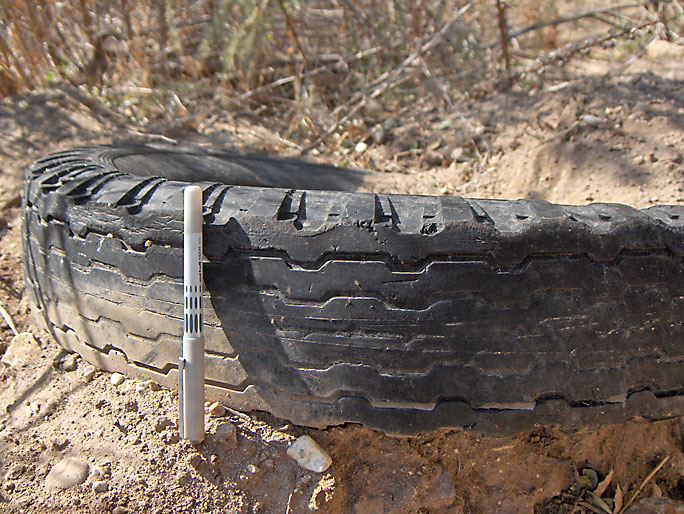
View of the tread on the tire (10/28/2007)
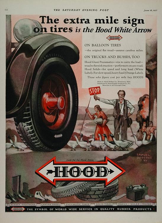
Hood White Arrow tire advertisement from 1927
I don't know what this is but it must weigh 50 pounds. I'm guessing that it was used by a blacksmith. Most old oil derricks had a blacksmith to make on the job repairs or fix the the cable tools. Jeff Brantly also suggested that it may be the lower part of a pitman that attached to the crank on the band wheel. (7/21/2007)
View of other side (7/21/2007)
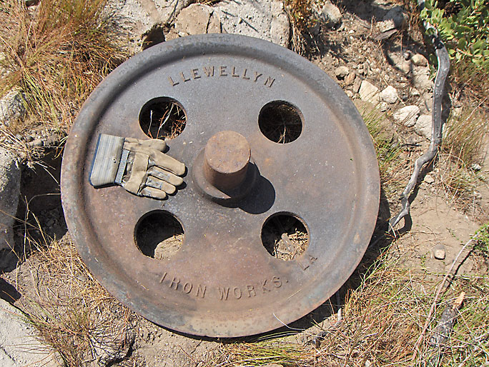
This is a 32-inch crown pulley. It would be located on the crown block at the top of the oil derrick with the rope or cable for the cable tools passing over it. It was made by the "Llewellyn Iron Works LA". Llewellyn Iron Works was started in 1887 by John Llewellyn and merged with Consolidated Steel Corporation in 1929. (7/8/2007)
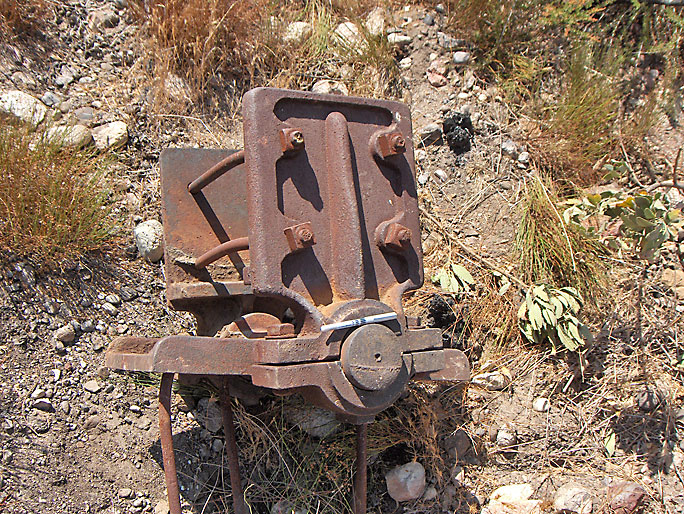
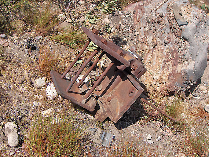
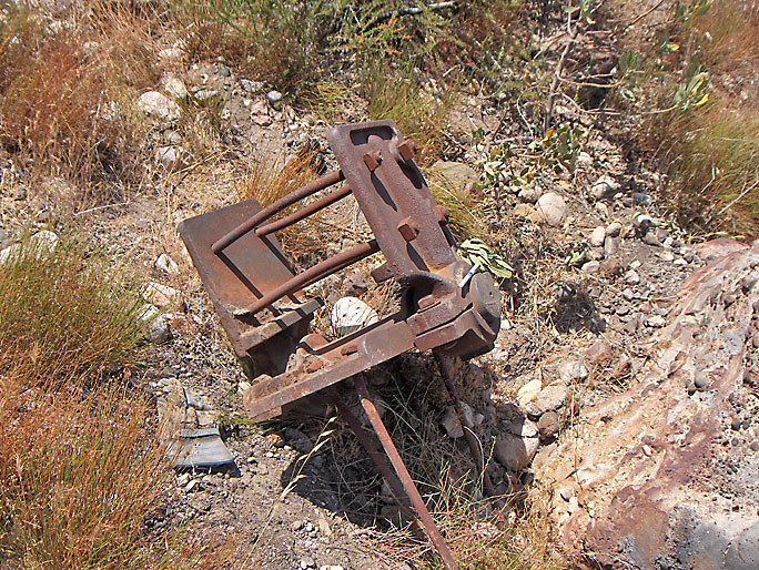
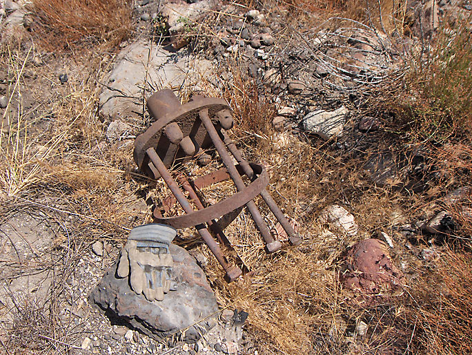
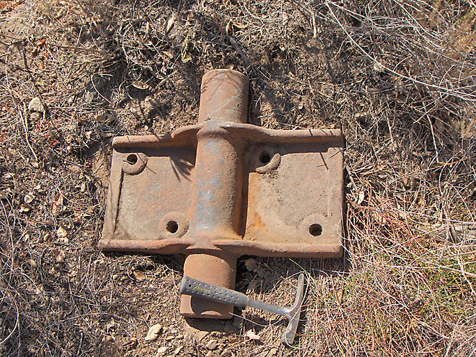
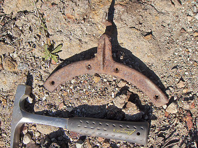
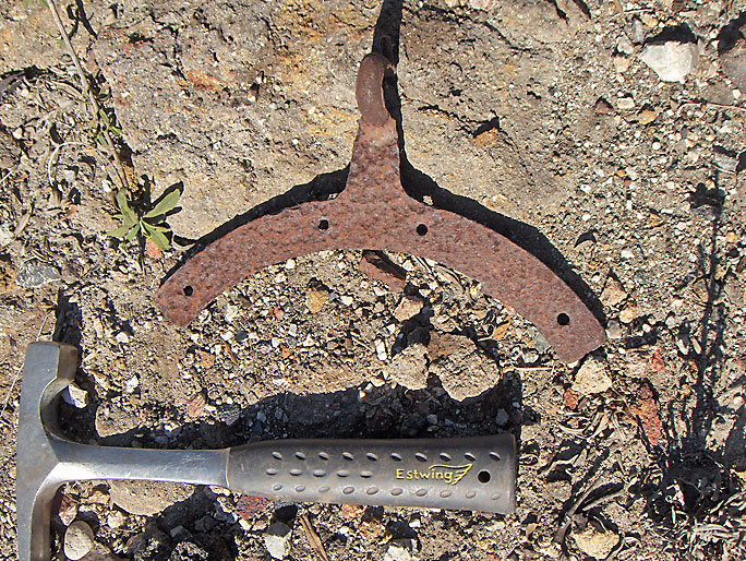
This is the supporting hardware (called "center irons") where the walking beam sits on the samson post. The walking beam would lie horizontally here attached with the lower long bolts and the samson post would be vertically below it. The hardware is upside down in the picture. (7/8/2007)
(7/8/2007)
(7/8/2007)
(7/8/2007)
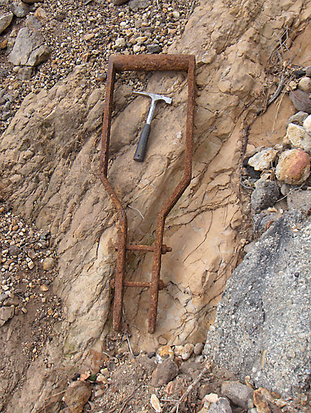
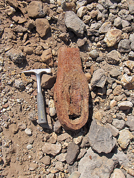
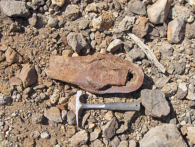
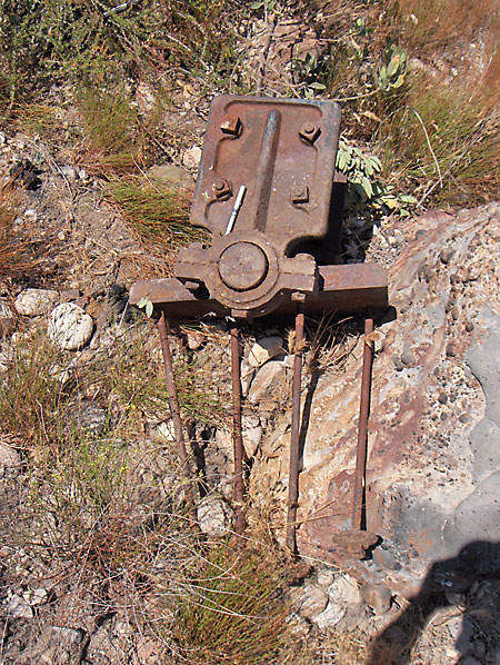
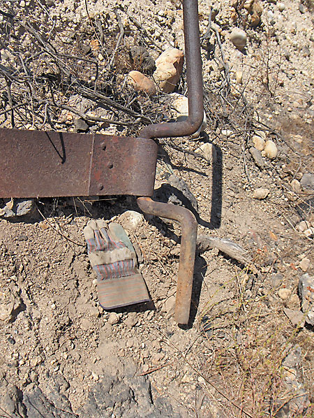
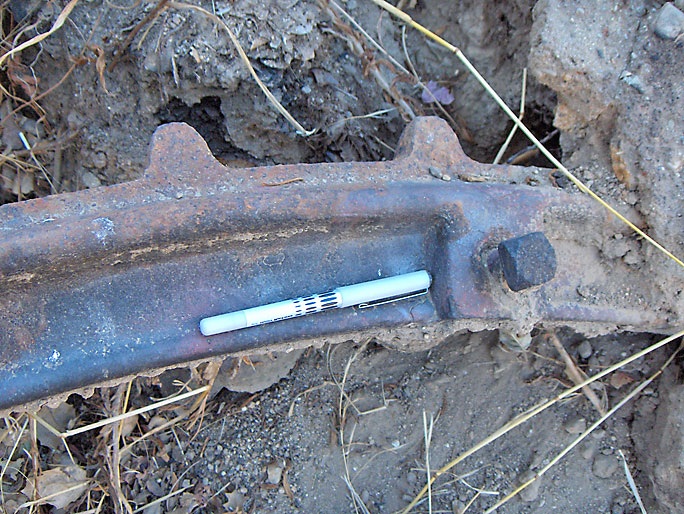
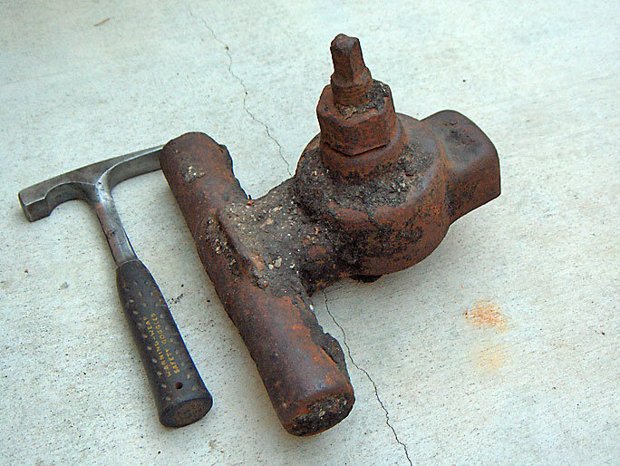
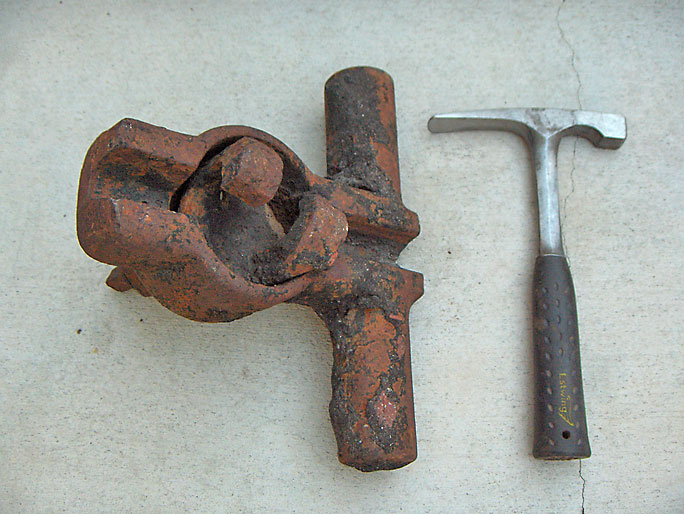
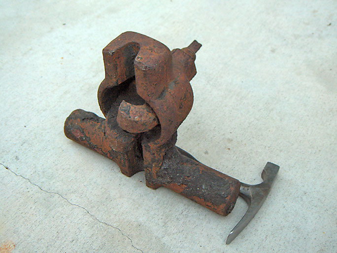
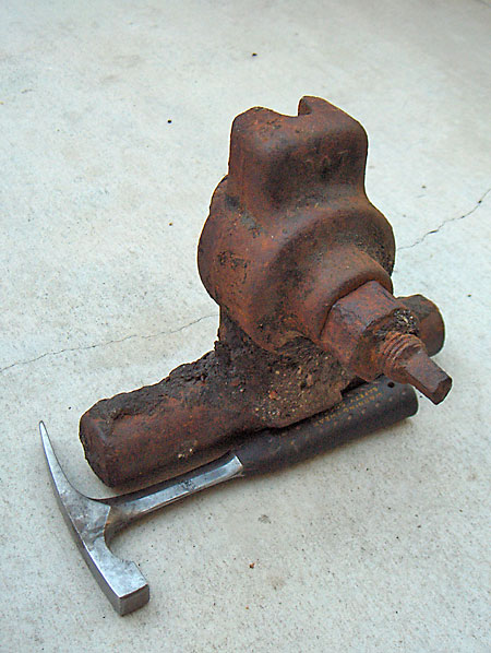
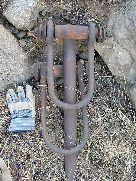
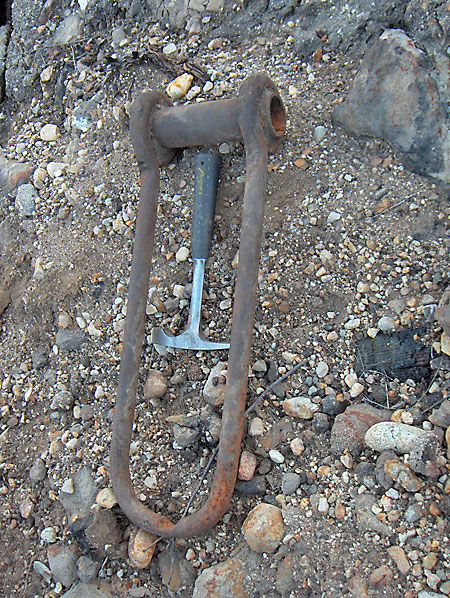
This is a walking beam stirrup used on the old cable tool rigs. It was fitted over the walking beam on the opposite side of the well head. The pitman would be bolted to the narrower part. The pitman was attached to the crank on the band wheel. As the band wheel turned (powered by the steam engine), the crank would cause the stirrup to go up and down, which caused the walking beam to go up and down. (9/29/2007)
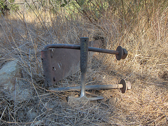
Gudgeon (7/8/2007
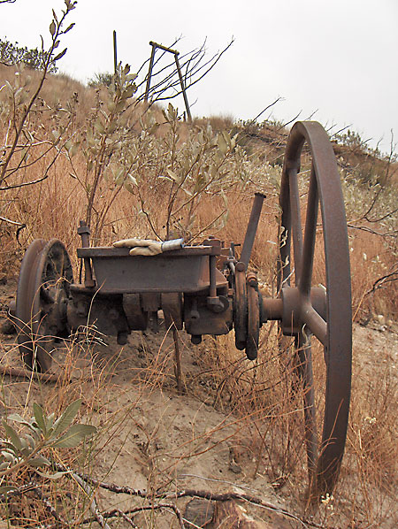
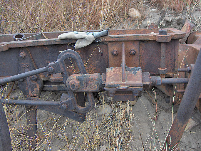
Brake band with brake band lever for a bull wheel (identified by Jeff Brantly). (7/30/2007)
The other end of the brake band with the staple (not from the above brake band) (9/16/2007)
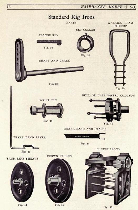
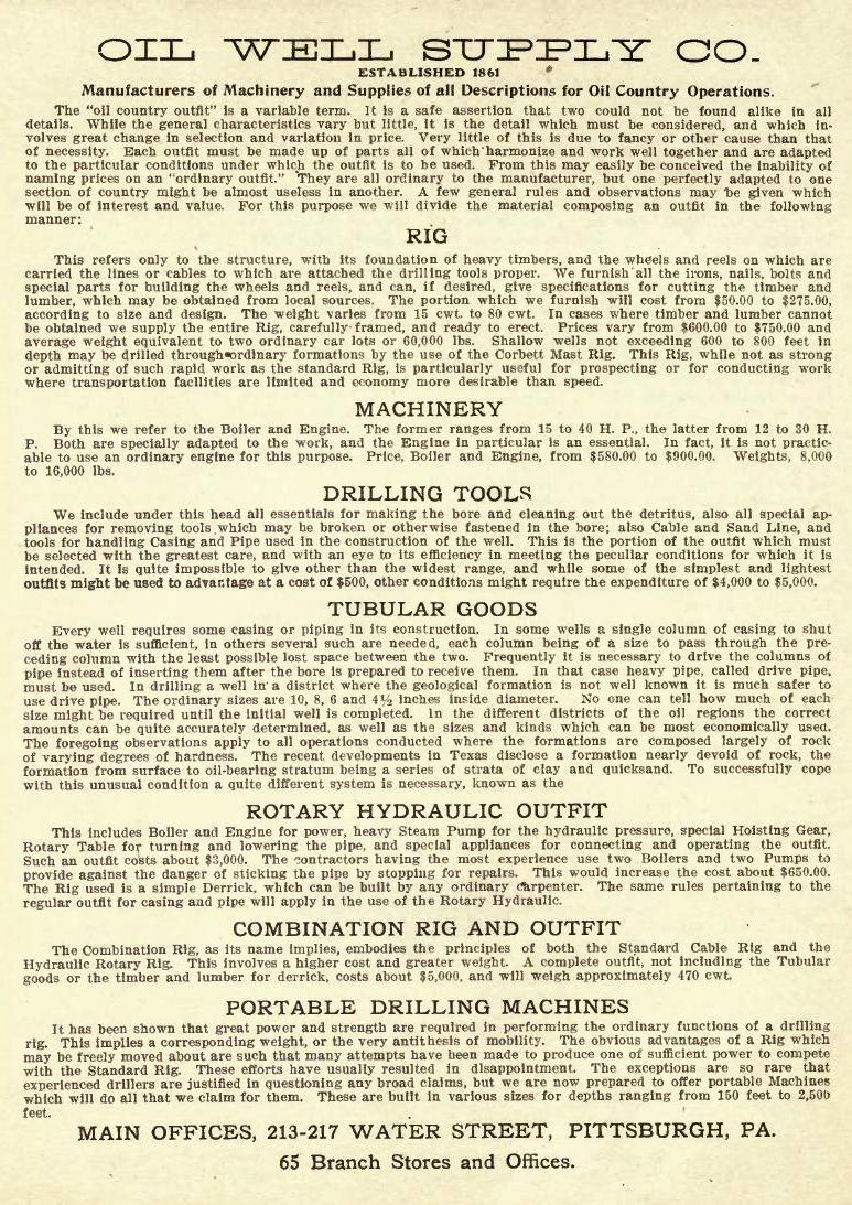
This page is from the Fairbanks, Morse & Co. General Catalog of Oil Well Supplies and Machinery of 1914. Notice the crown pulley, the center irons, the walking beam stirrup, the bull or calf wheel gudgeon, and the brake band lever.
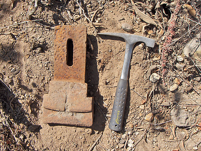
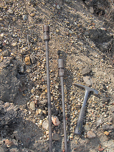
This is one (of two) cutters from an under reamer drill bit for a cable-tool rig. Reamers enlarge the diameter of existing well holes. An under reamer drills a hole larger than the casing through which it was passed. After it is lowered through and out the bottom of the casing, the cutting structure is extended outward. It then cuts a hole larger than the casing's outside diameter so that the casing may be lowered. (7/30/2007)
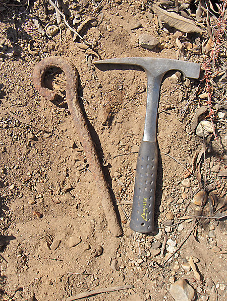
Eye bolt maybe from under reamer bit assembly. Found near above cutter. (7/30/2007)
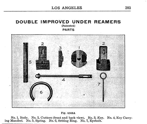
The cutter is number 2 in this partial page from the Union Well Supply Co. Catalogue A of 1912. The eye bolt is number 7.
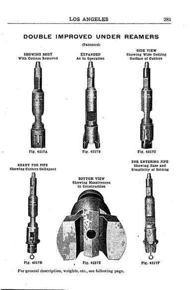
View of complete under reamers from same catalog.
This is part of the center irons (called the "saddle") and would be bolted to the bottom of the walking beam on the flat side. See a few pictures above for a more complete set of center irons. This was the only piece at this particular well location. (7/30/2007)
This is a sprocket tug rim probably from a calf wheel. (2/6/2012)
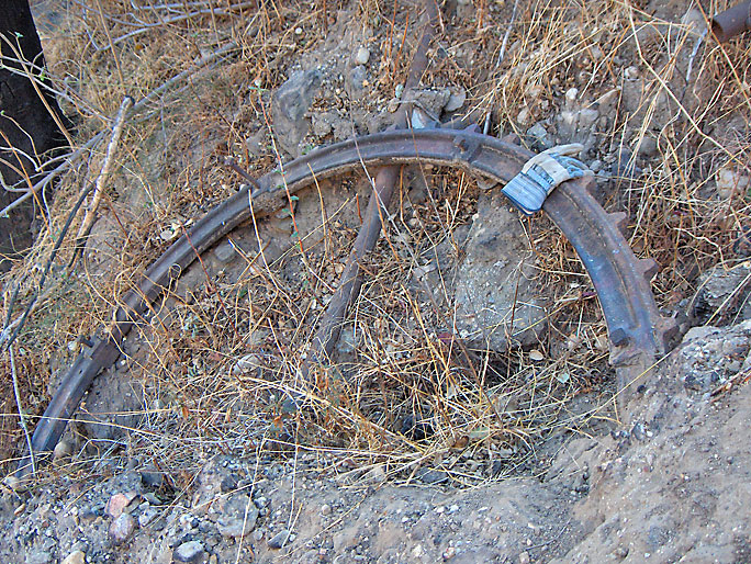
Another view of the sprocket tug rim (2/6/2012)
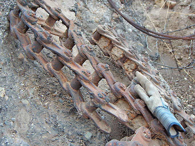
Chain near the sprocket tug rim. This chain probably mounted on the sprocket tug rim and turned the calf wheel. (2/6/2012)
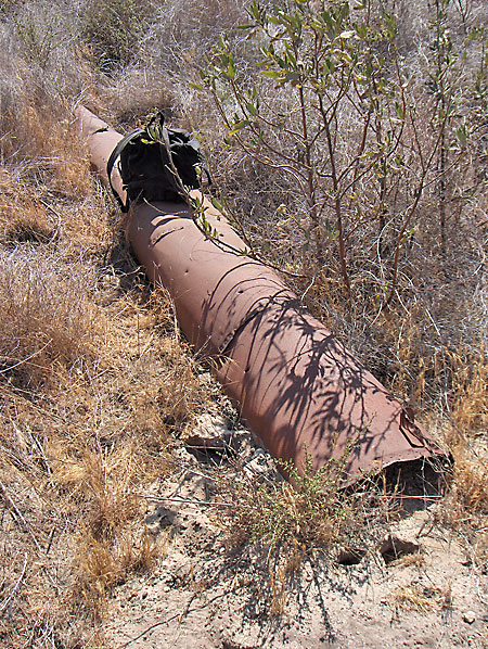
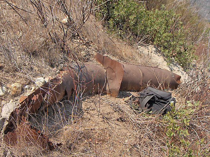
Pipes over the side of an abandoned well site. Pipes are a common sight in Elsmere Canyon. (2/6/2012)
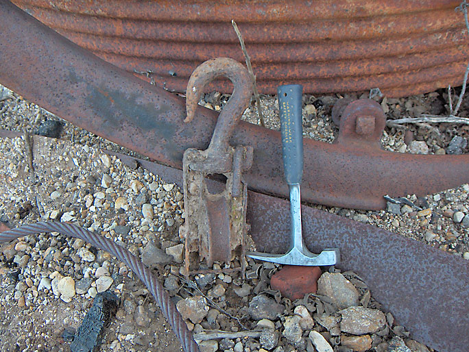
Clevis (6/16/2007)
A clevis could be used on a jack line, like this one. (5/26/2007)
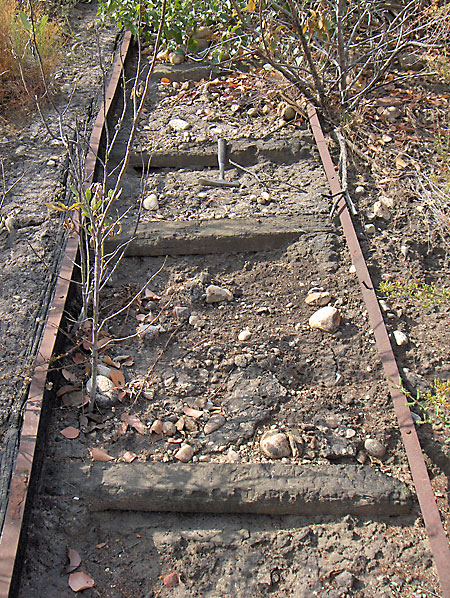
This is some sort of old track. The metal slats on each end are nailed to wood. (5/26/2007)
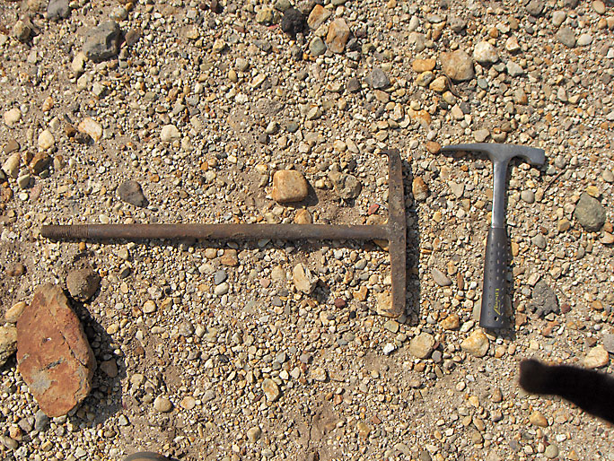
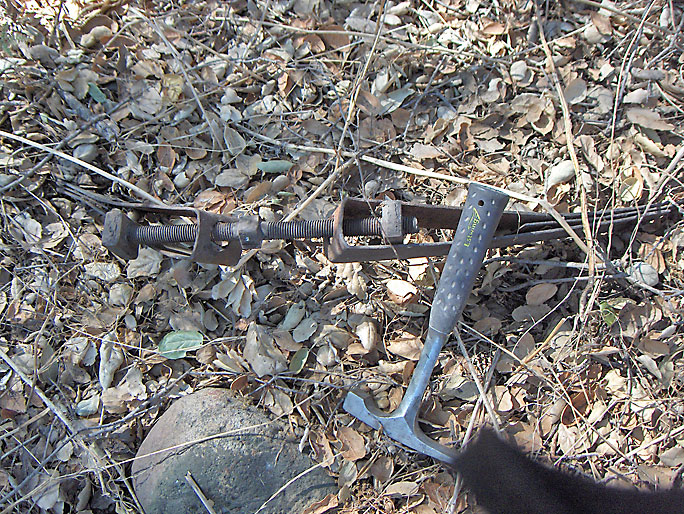
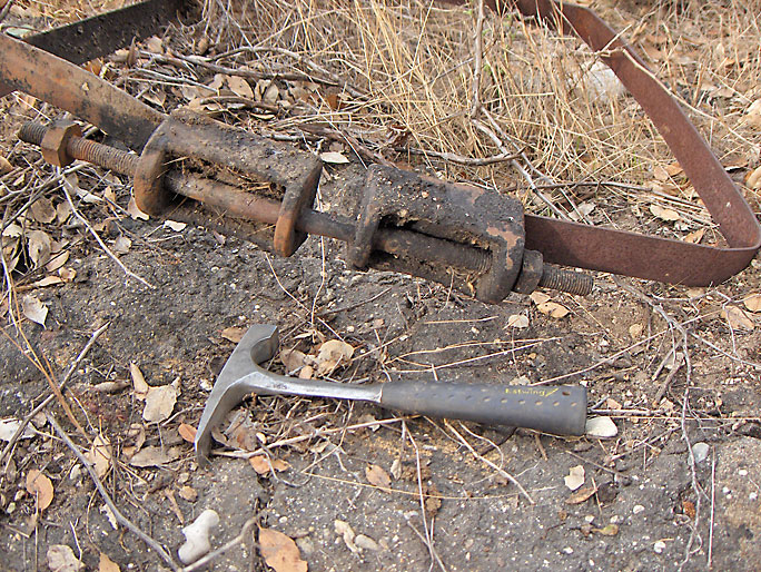
Adjuster for a pumping oil well. It would be placed in a vertical position on the top of a walking beam at the pumping end. It was held down by an adjuster board. The adjuster board was bolted to the walking beam by an adjuster T-Bolt. This is a Lewis patent style adjuster. (7/30/2007)
The underside of the adjuster showing where a "polished" rod would be held in place
This is how the adjuster would be sitting on the walking beam
The opposite sitting view. See the pumping well diagram which shows how everything fits together.
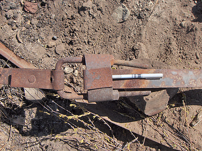
Adjuster T Bolt. This is what held down the adjuster board that held down the adjuster from the previous pictures. It goes into a hole in the walking beam with the threaded part on top. (5/26/2007)
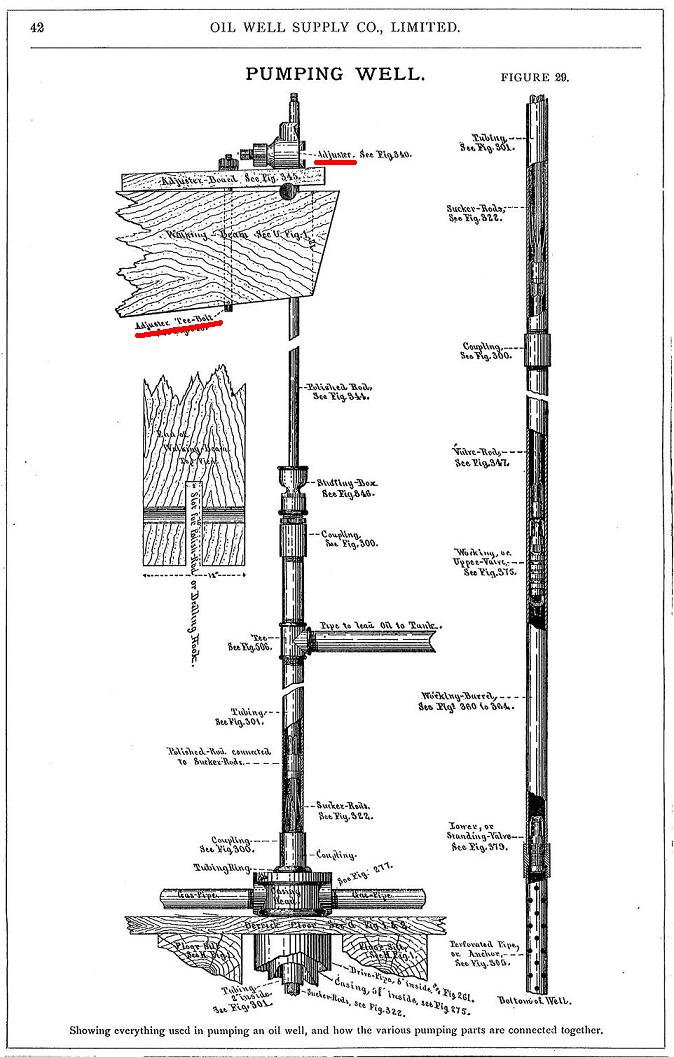
Pumping well diagram from the Oil Well Supply catalog of 1892. Note the adjuster at the top of the diagram on the walking beam and the adjuster Tee-bolt.
Ratigan No. 2 polished rod clamp. It supports the column of sucker rods from a well being pumped when the connecting mechanism is disengaged from the rods. (1/19/2008)
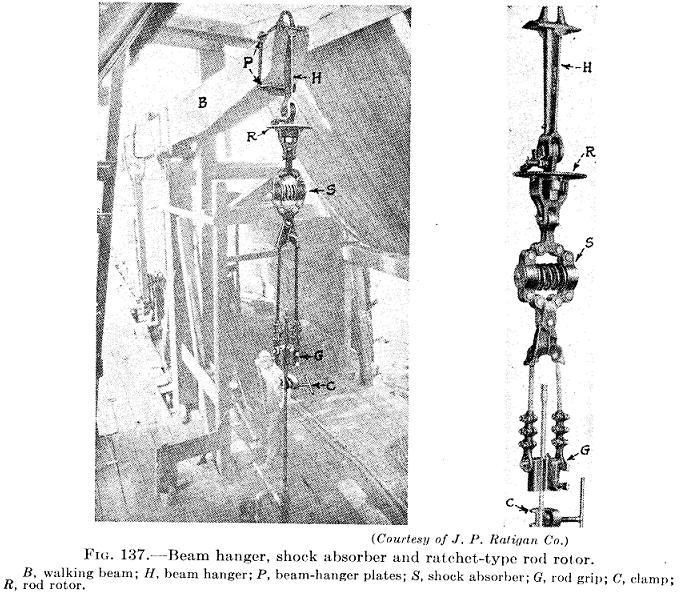
Ratigan diagram showing polished rod clamp (C) from "Petroleum Production Engineering: Oil Field Exploitation", by L. C. Uren, 1939
Oil well pump sucker rods. About 25-ft long with male and female end so sections could be screwed together to be lowered into well as part of the pumping device. Sucker rods were also sometimes used as jack lines (see Jack Plant page). (5/26/2007)
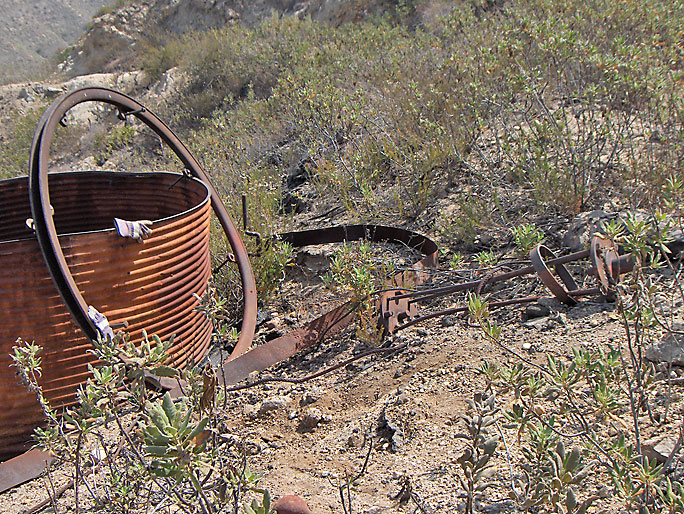
A old tank, a bull wheel brake band at the base of the tank, a calf wheel rim about 7.5 feet in diameter laying on the tank, and a set of gudgeons probably for a bull wheel. (5/26/2007)
Casing head (identified by Jeff Brantly), gudgeon, and two sections of a calf wheet rim in a gulley below a well site. (12/16/2007)
Block (or pulley) possibly from old derrick (2/4/2007)
Pipe saddles (2/10/2007)
Hoop connection for a wooden tank. This style is in an 1884 oil well supply catalog which called it a "Ware's patent tank hoop connection." (9/1/2007)
Another kind of hoop connection for a wooden tank. This one looks like an even older style then the previous one, but I havn't seen it in any supply catalog. (9/16/2007)
Still another kind of hoop connection for a wooden tank. This single bolt hoop connection appears in a 1912 oil well supply catalog. (9/29/2007)
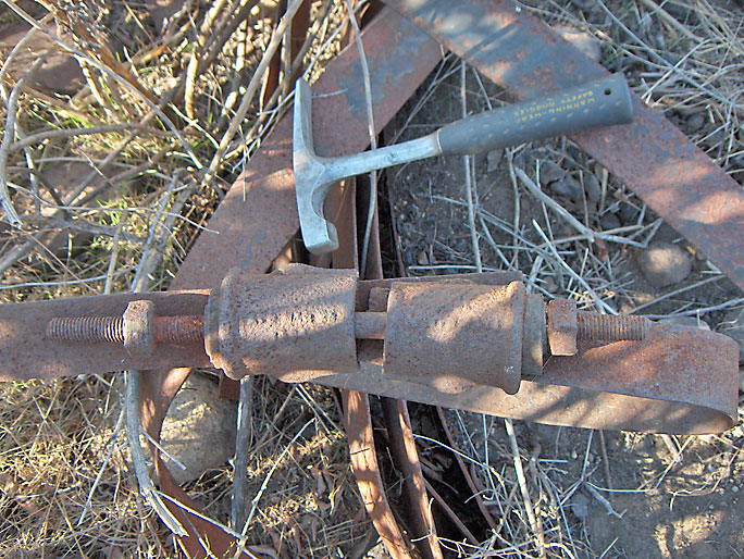
A fourth kind of hoop connection (10/28/2007)
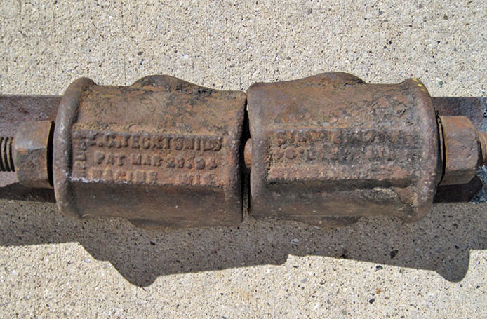
Here is a close-up of the fourth kind. It says "EC Tecktonius Mfg Co
Pat Mar 20 04 Racine Wis". The E C Tecktonius Manufacturing Company of Racine, Wisconsin, was established in 1891 by Emil C. Tecktonius (1846-1920). It was still in business in the 1960's. The patent (No. 759328) was actually given on March 10, 1904.
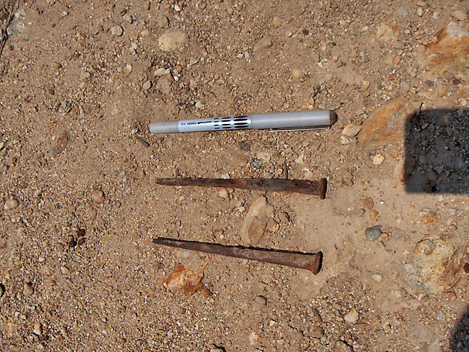
Old "cut" nails (8/4/2007)
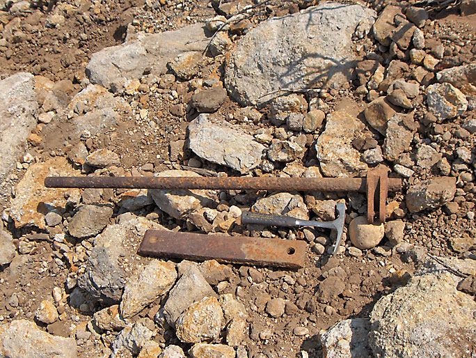
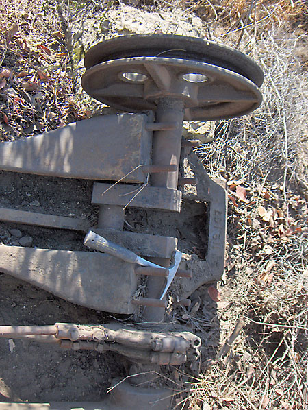
This shaft and rectangular shaped hardware is on a slope below an old well location. (8/4/2007)
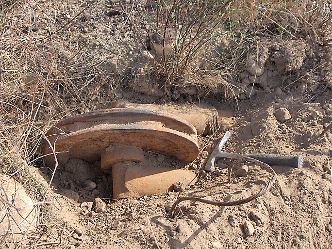
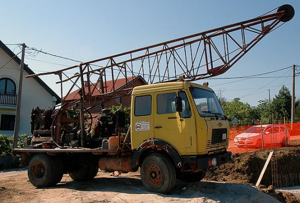
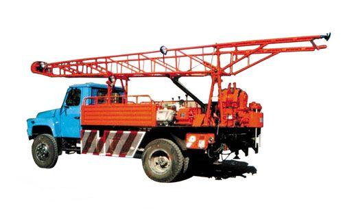
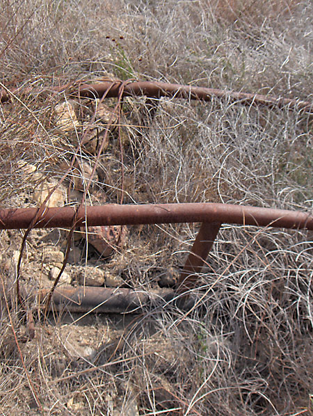
This is a single 18 inch diameter pulley (or more correctly called a sheave) on top of the tallest structure in the Elsmere oil area - an A-Frame (or gin-pole) derrick. It is located near the boiler and the separation tank where it is covered with brush and partially buried. There are still support cables wrapped around it. Based on the way it's been constructed (one-piece with everything welded together), I believe it would have to date later than 1930. It could be used as a portable cheap drilling rig or a pulling rig. These wells were leased by Stough & Hutchinson between 1943 and 1944 (when they went out of business) and then by the York Oil Company from 1944 to 1946. More than likely one of these companies dumped this here. (10/28/2007)
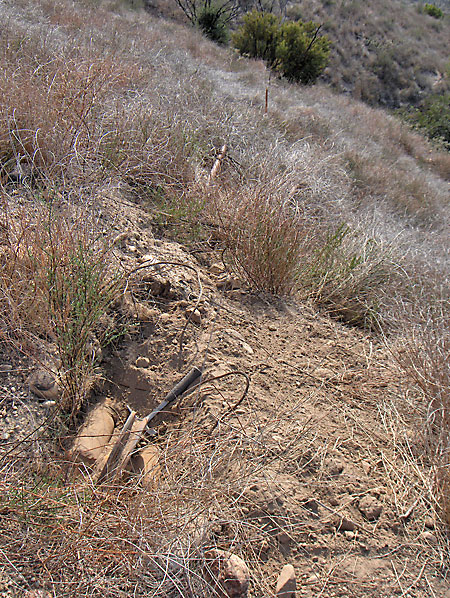
Looking from the pulley to the end of the rig at the red marker. It is about 42 feet long in an A-frame shape. (10/28/2007)
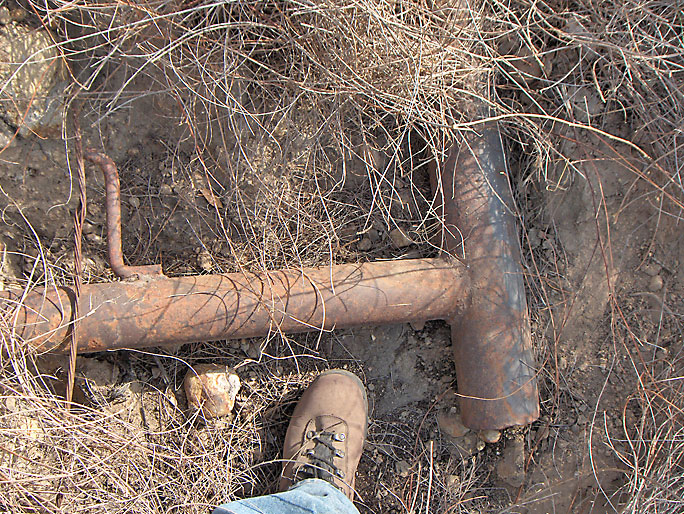
Here is the 7 foot base consisting of a 4.5 inch diameter pipe. Welded to the base about 6 inches from each end are two 3.5 inch diameter pipes. The two pipes slowly angle up to the top where they support the pulley. Every 7 feet or so a cross beam is welded between them for support. (10/28/2007)
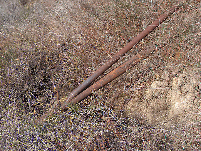
At about 9 feet from the base is a pipe 2.5 inches in diameter pipe welded to both of the main pipes. These pipes go away from the main pipes at a maximum distance of about 1.5 feet and then eventually join back together near the top. (10/28/2007)
There are supports welded between the main pipes and the secondary pipes. (10/28/2007)
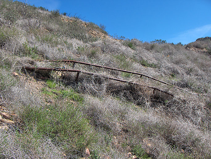
Another view of structure. (2/9/2008)
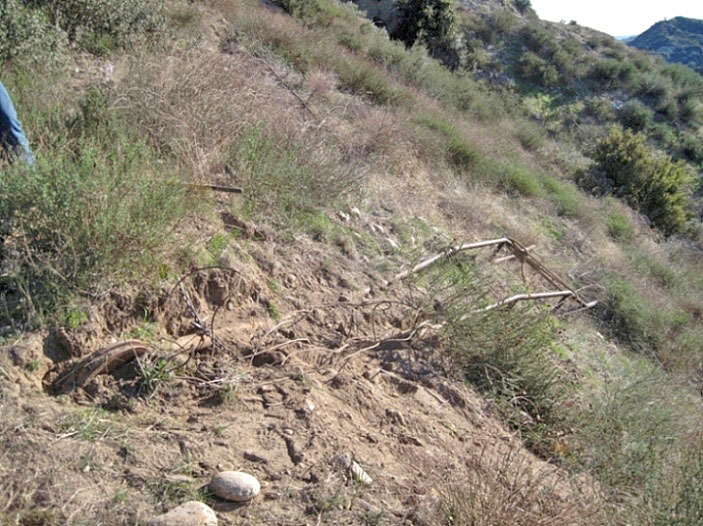
During the cleanup after the well abandonments of December 2011 through January 2012, the rig was pulled out of its resting place and left near the ranger's house in Whitney Canyon. Here, they (the cleanup crew) have partially dug it up and are attaching a chain to pull it out and up with.
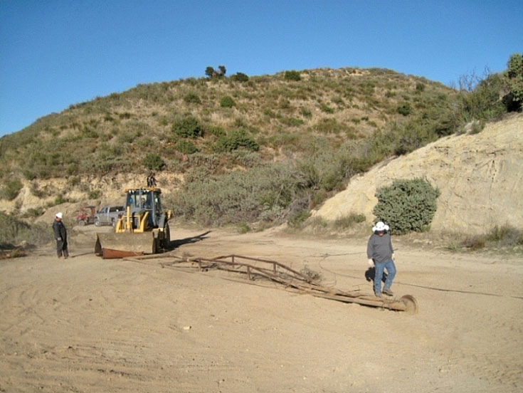
Here it is on the flat area after they pulled it out (on 1/9/2012). The next day it was trucked over to Whitney Canyon.
Here are two examples of truck mounted rigs similar to the above rig.
A D-link. Based on where I found it, it probably was part of a jackline support. (11/11/2007)
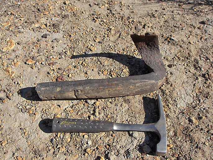
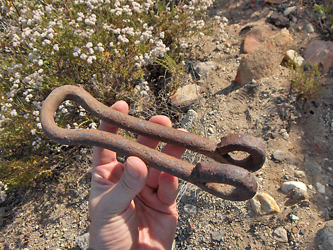
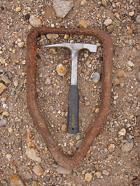
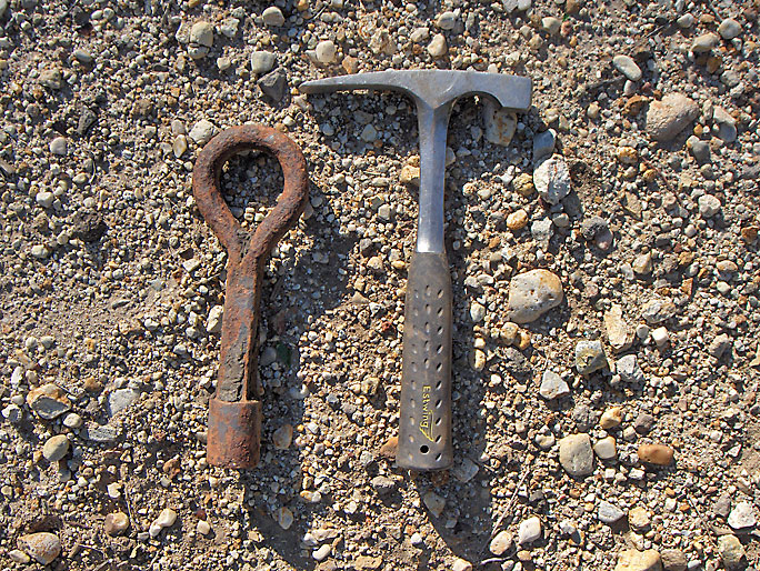
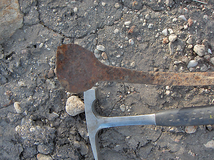
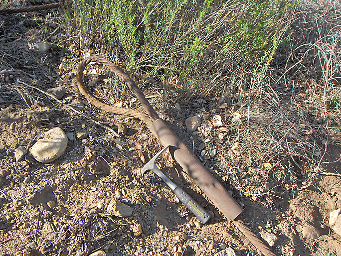
This appears to be a hand wrought metal tool found at a circa 1900 oil well site.I haven't found anything like it in any of my oil supply catalogs but it looks like it may be the end of a fishing tool. Fishing tools were used to recover tools, cables, pipes or rods which had become detached or stuck in the well. Many were built for specific fishing jobs and this may have been one of those. One thing for sure, it was originally straight and was bent to its present shape. This means that the site probably had a forge, which was common in those days. (11/23/2007)
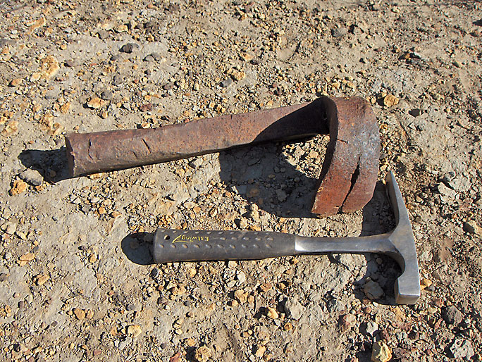
Another view of tool (11/23/2007)
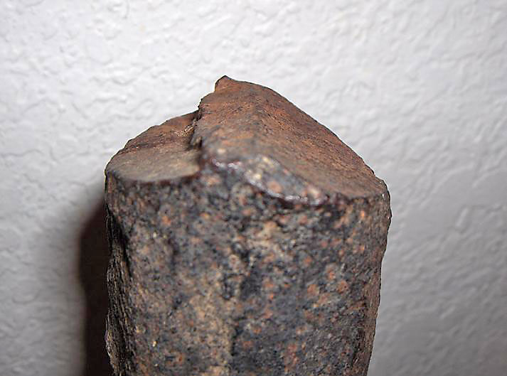
At the oval end of the tool are these slanted cuts, kind of like when a tree is cut down, so it would appear to me that the tool was originally longer (or possibly the tool was suppose to be this size and was cut from a longer piece). (11/23/2007)
Small metal arc with hook used on a circa 1900 oil rig. The four beveled holes were probably for wood screws. At first I thought it may be a small wrench circle, but Jeff Brantly pointed out that it was too small and thin for that. What it was used for is unknown to me. (12/24/2007)
Another view showing the flat side that would face the wood base with the hook part overhanging. (12/24/2007)
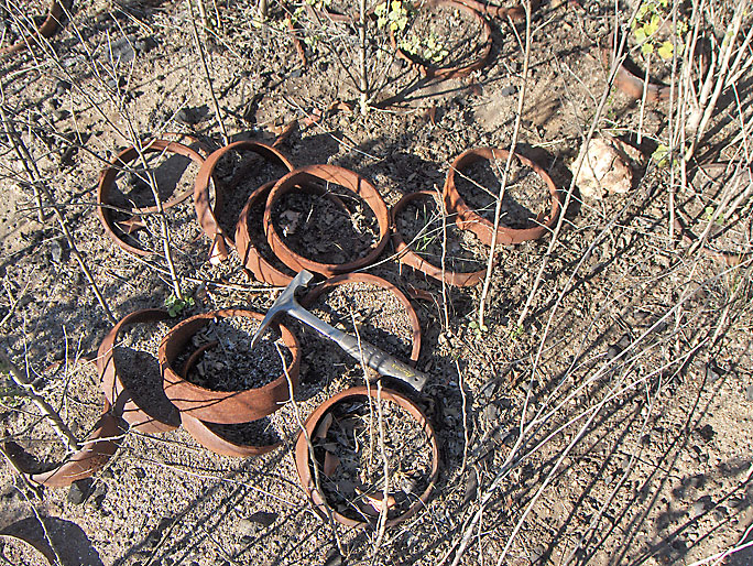
On a 1900 oil rig site is this pile of about 30 probable thread protectors for casing (with thanks again to Jeff Brantley). They would keep the casing threads from being damaged. I have never seen this many together in one place before. It shows that this site has not been visited by humans in a very long time, maybe since the early 1900's. The well was barren and abandoned probably in 1900 or 1901. (12/24/2007)
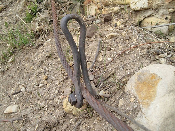
Jeff identifies this as a pull strap from a pump jack. The worn loop part is where a connector hooked the pull strap to the jackline. It was found directly below a well location that was pumped using a jackline. (12/16/2007)
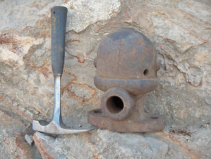
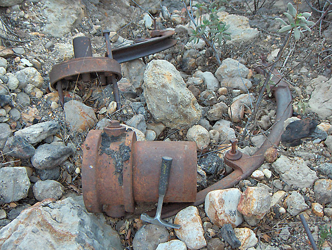
This looks like an air chamber for an engine pump. It is 7.5 inches tall with the main hollow "hat" being 4.5 inches in diameter. The number "32" is on one side. (12/16/2007)
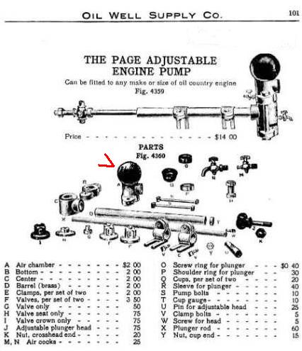
The air chamber is "A" in this diagram from the Oil Well Supply Company catalog of 1907. It looks very similar to the above artifact.
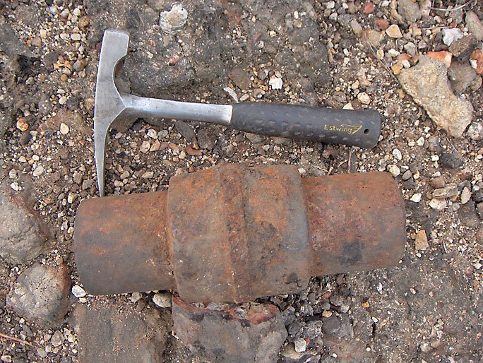
Heavy cylindrical piece of metal 11 inches long. The end diameters are 3.5 inches and the middle has a diameter of 5 inches. (1/1/2008)
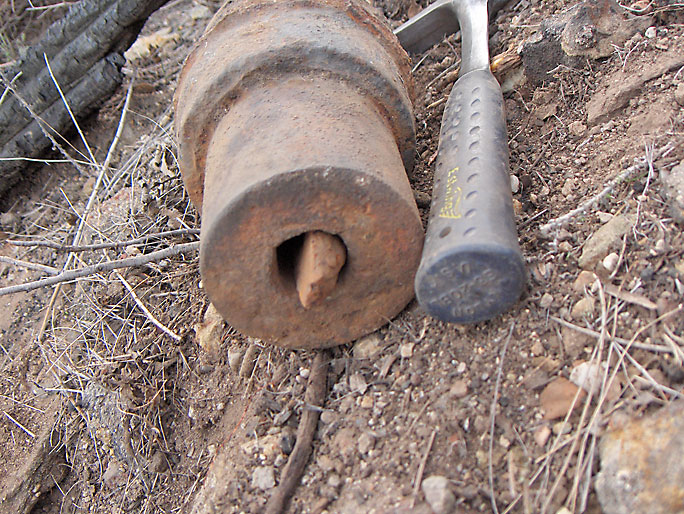
Another view showing a small about 1 inch hole that extends all the way through the center of the cylinder. Inside, the hole has a slight bulge containing this metal piece which is too large to come out of either end. Whether it is supposed to be in there I don't know. (1/1/2008)
Loop with female socket. Jeff Brantly believes that a hook similar to the two following hooks were screwed into a piece like this. A line would be pass through the loop and the tool would be lowered into the well as a bailer or sand pump grab. (12/15/2007)
Hook about 2 feet long and threaded on one end. Probably used with a loop similar to the previous loop. (12/8/2007)
Hand wrought hook threaded on one end used on a circa 1900 oil rig. Also probably used with a loop similar to the previous loop. (12/24/2007)
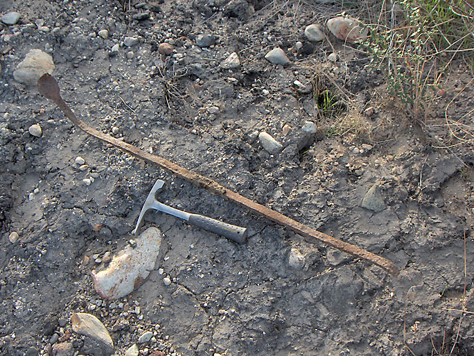
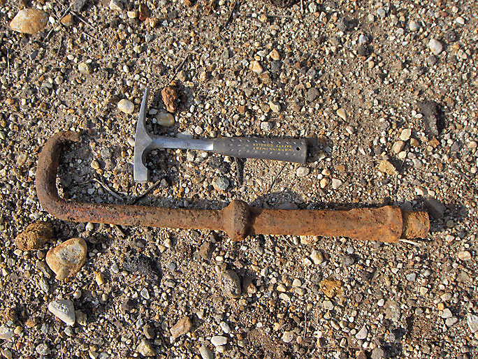
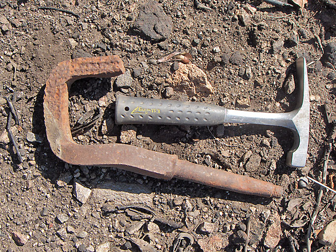
Crowbar from 1900 well site (1/1/2008)
Closer view of "scoop" end (1/1/2008)
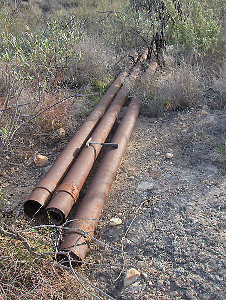
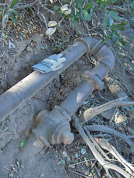
Group of about 20-foot long pipes near jack plant and Clampitt 12 oil well. The outer 6-inch diameter pipe contains an inner 4.5-inch diameter pipe. These were probably removed from Clampitt 12. (1/1/2008)
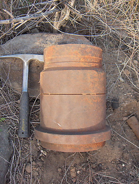
This modern looking artifact is one foot long with an 8-inch outside diameter. The last well drilled in the area where this was found was in 1979 - Margaret Bath 1. (1/1/2008)
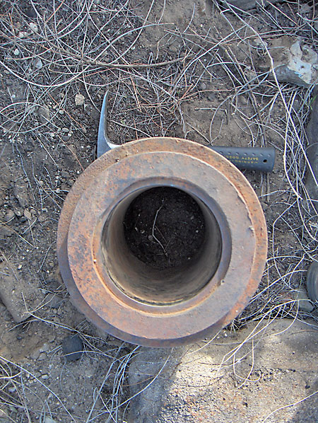
The inside is lined with a shiny metal - stainless steel? (1/1/2008)
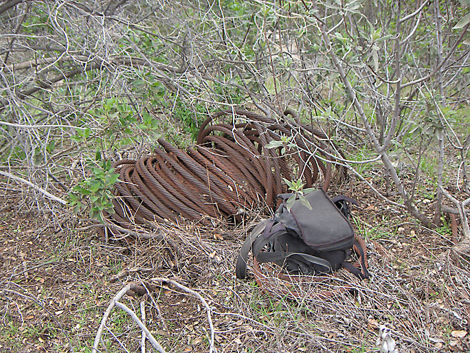
Large bundle of 1-inch diameter steel rope (2/23/2008)
Large loop in steel rope (2/16/2008)
Oil Well Supply Company advertisement in 1905 publication
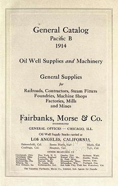
Fairbanks-Morse Pacific Catalog: Oil Well Supply Edition 1914
View and/or download this catalog from the Internet Archives website. It contains much old oil well hardware information.