Cable Tool Rig
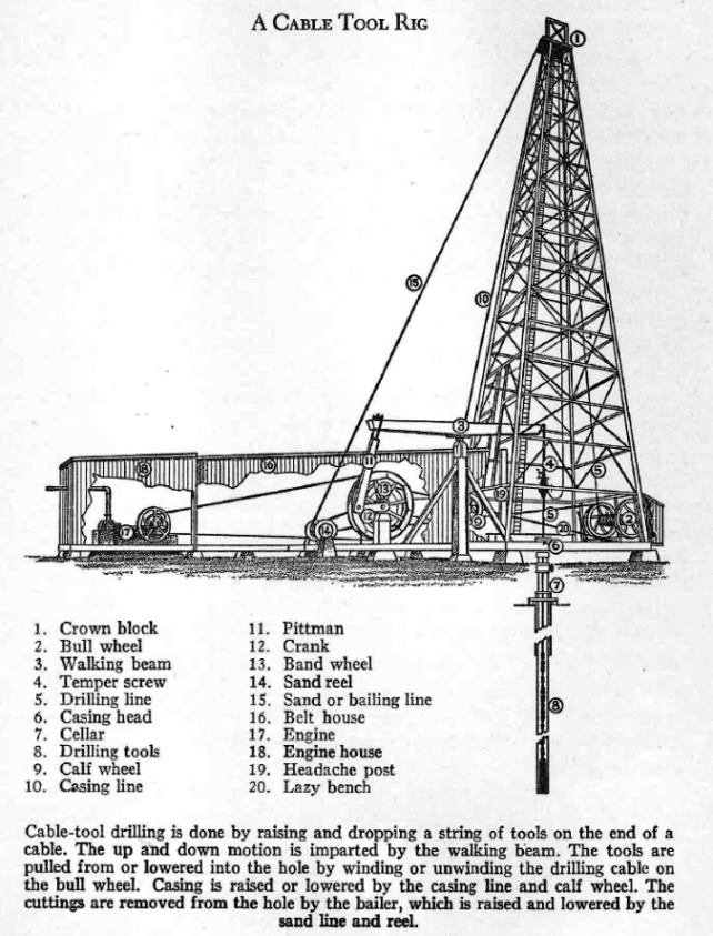
Cable tool rig diagram from This Fascinating Oil Business by Max W. Ball, 1940, The Bobbs-Merrill Company, p. 103
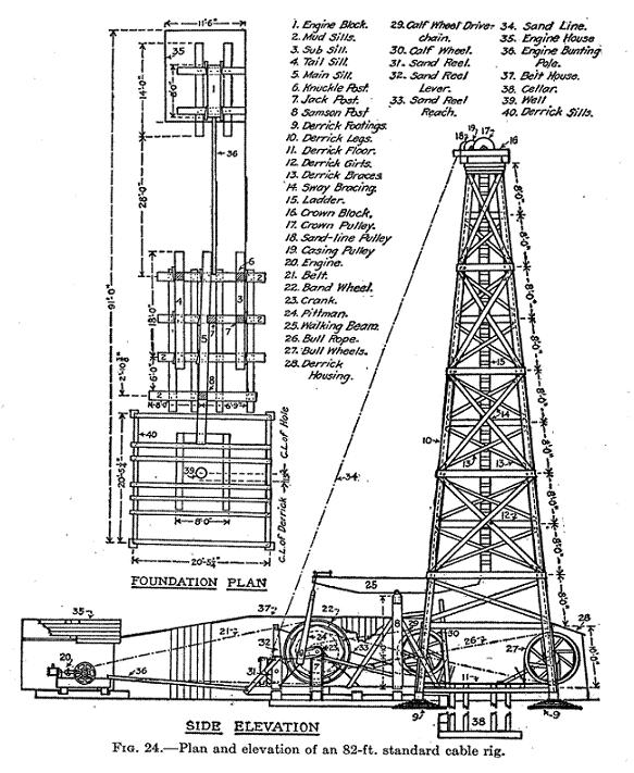
Detailed standard cable tool rig from Uren, Petroleum Production Engineering, 1946 (see oil sources)
Cable tool rigs were widely used from about 1870 and are still being used today, although almost all of today's oil wells are drilled using a rotary rig. All the pre-1950 Elsmere Canyon wells were drilled with cable tools rigs. The basic machinery consisted of the engine and boiler, the derrick and crown block, the bullwheel and drilling cable, the sandwheel and sanding line for the bailer, the vertical bandwheel with a center crank, and the walking beam supported by the samson post. Bandwheels were essentially large pulleys (usually 8-10 ft in diameter) driven by a leather belt from the engine, which reduced the engine rpms and increased power. A crank on the bandwheel's axle imparted up-and-down motion (via a pitman) to the walking beam, the other end of which was connected to the drilling cable by the temper screw. The walking beam alternately raised and lowered the drilling tools. Walking beams were typically 26ft x 12in x24x in size. Bullwheels and sandwheels were spools for the drilling cable and sanding (or bailing) line, respectively. Additionally, fishing tools, various hand tools, wrenches, and forge tools were required for the drilling process.
"Spudding" was the process of starting the oil well. Since the complete string of cable tools was 40-ft. long or more, there was not enough headroom to drill with the walking beam until a depth of at least 60-ft. was obtained. The first 60-ft to 100-ft. was therefore drilled by spudding, a process that did not involve the use of the walking beam. Below is a typical spudding rig setup (from Uren, 1946 - see oil sources). A special spudding bit is used along with a special set-up (see below). The crank was disconnected from the walking beam and a rope was connected between it and the drilling cable. The crank jerked the rope on each revolution, which in turn jerked the drilling cable and caused the drill bit to rise and fall in the hole. As the well got deeper, the bull wheel (which holds the drilling line and had been locked in place) was released to let more cable out. When the well became too filled, this process was interrupted to bail out the loose material.
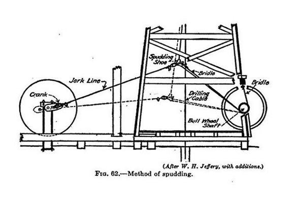
When the right depth had been reached, the spudding equipment was removed and the complete set of cable tools with a normal drilling bit were assembled and carefully lowered into the well. This was called "hitching on". The drilling bit, along with the cable, could reach weights of 3600 lbs or more.
The early rigs were powered with steam. Steam was delivered from the boiler to the engine by way of pipe. The engine powered the band wheel by a turning belt. A well-braced upright post, called the sampson post, was mounted further down the platform. On top of it, and mounted with a hinge, laid the horizontal walking beam. The band wheel was connected to one end of the walking beam by a pitman and crank. As the band wheel turned the crank, the pitman was raised and lowered which rocked the walking beam up and down on the sampson post like a teeter-totter. A temper screw was attached to the other end of the walking beam. At one end of the temper screw there was a clamping device that gripped the drilling line to which the cable tool bits were attached. The drilling line came from the bull wheel and ran over a pulley at the top of the derrick. The bits, which were basically just pointed steel weights, pounded the well into the ground. The action at the bottom of the well was one of crushing, not chipping or cutting of the rock. The walking beam raised and lowered the bits about two feet. If the complete drilling tool string weighed 1200 lbs (and some weighed up to 3000 lbs) and the velocity was 6 feet per second, the the force of the blow would be over 16 tons. After a while, the bit had to be replaced. In soft formations, progress could average 30 feet per day, sometimes less, sometimes more, depending on the conditions. The equipment was run 24 hours a day.
The drilling was controlled by a skilled worker who, by feeling the line from time to time, could tell what was going on in the well. When necessary, he could let out more line or stop the walking beam. When the bottom of the hole became clogged with rock chips, the bit was raised and a bailer (attached to the the sand line on the sandwheel) was lowered into the well to scoop out the debris. This involved a complicated process of raising the drilling cable with bit out of the well and lowering a bailer bit from the sand line. The bailer then had to be lowered and raised multiple times until it collected enough material. Then it had be raised out of the well and emptied. This had to be done until the well was cleared of loose material. After that, the drilling cable was lowered into the well and the whole process started again. This pound and bail process was repeated about every three feet.
The calf wheel contained the casing line. When casing was necessary for the well, the casing line was used to lower it into the well. The headache post was a safety feature that kept the walking beam from dropping if anything came loose at the other end of the beam.
As greater depths were reached, control became increasingly difficult. The cable became longer, heavier, and had more elasticity. Water often become an issue. Subsurface pressures could not be controlled causing frequent blowouts. An experienced driller was a big asset.
In 1914 the usual cost of drilling a 1000-2000 foot hole with cable tools was about $10,000 - $30,000. Prior to 1910, practically all wells in California were drilled with cable tools. Not until about 1914 was rotary drilling generally adopted. By 1930, over 95 percent of all wells were drilled by rotary rigs. Today, cable tool rigs mainly drill water wells and other non-oil holes.
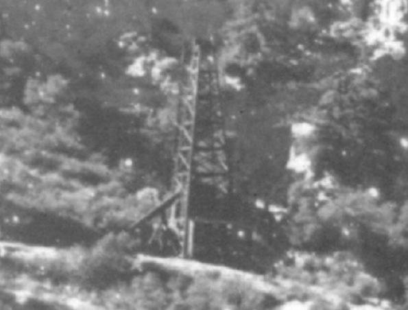
One of the derricks from the 1905 Ralph Arnold photo (see historic photos page) blown up to show details. The teeter-tooter
like structure to the left of the derrick is the a walking beam. Note that there is no machinery giving the power to the walking beam. Based on the derrick's position, this must be Elsmere 18, drilled in 1900 and probably pumped by a jackline in 1905. The picture is not clear enough to see the pump.
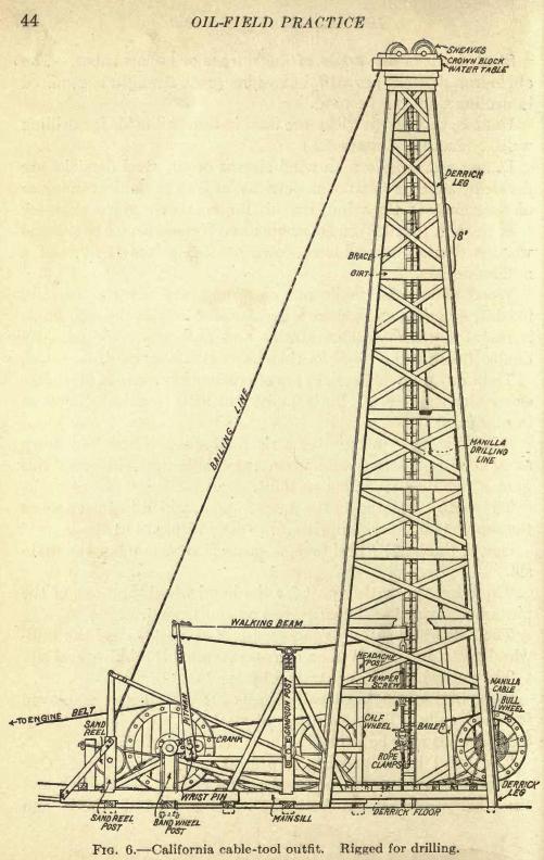
A California cable tool rig diagram from "Oil-Field Practice", by Dorsey Hager, 1921 (see sources)
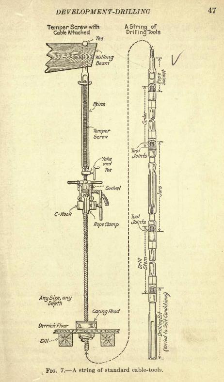
A cable tool string also from "Oil-Field Practice" by Hager
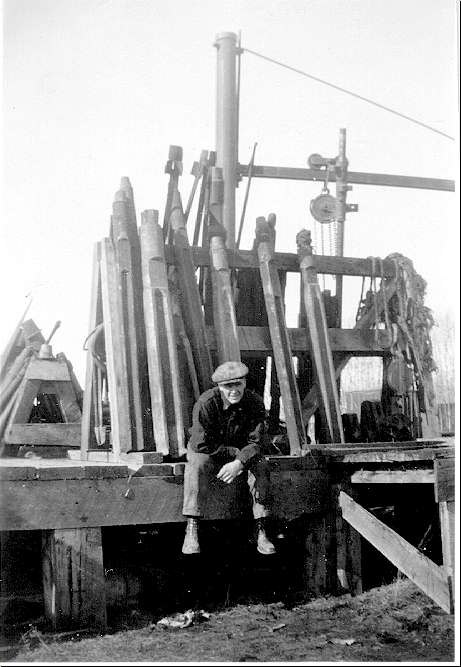
Old picture of cable tool bits
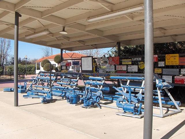
Cable tool bit display at the Kern County Museum in Bakersfield
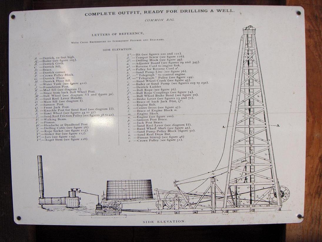
Cable tool rig chart at the Kern County Museum in Bakersfield. Note that there is no calf wheel.
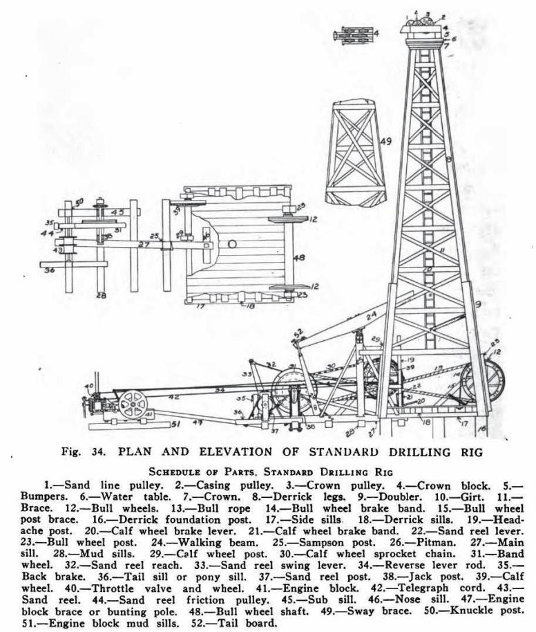
Another nice chart of a standard cable-tool rig form Oil Production Methods by Paine and Stroud (1913)
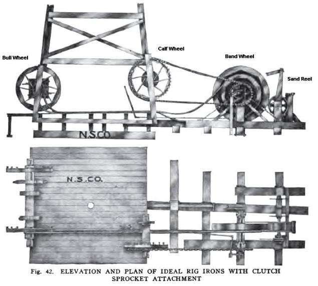
Side and top view of the set-up of the four wheels
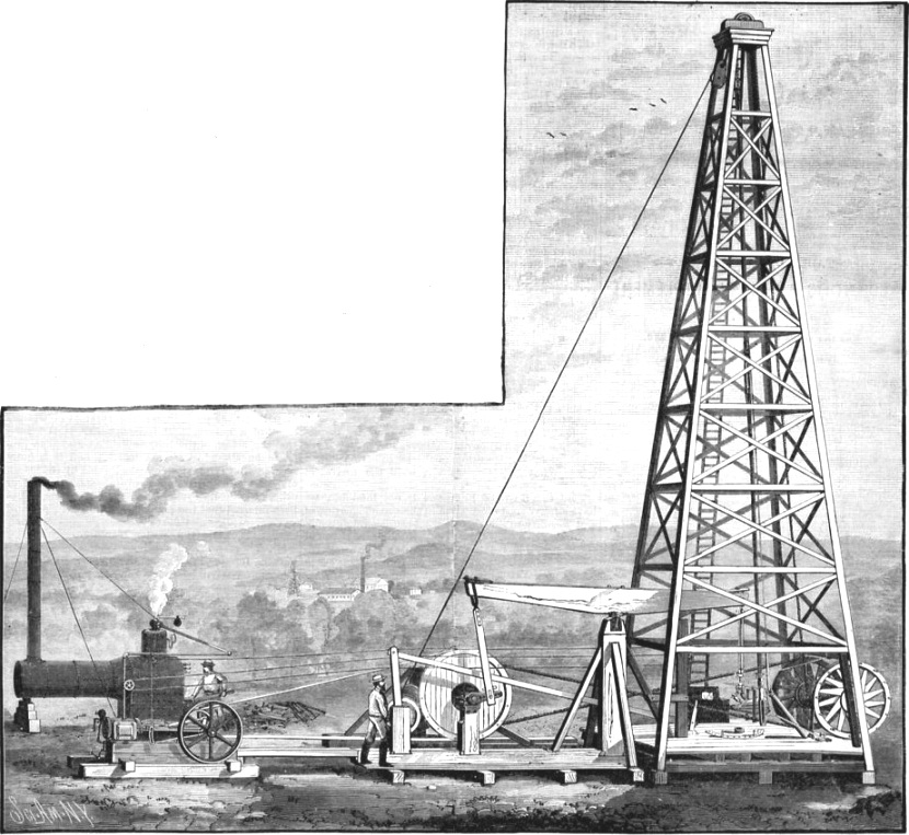
No calf wheel on this rig from the front cover of Scientific American of August 21, 1886


